Talk To Our Expert, Get A Solution in 20 minutes
Share your LED screen needs. Our experts will provide solutions and a quick response.

Author: Senior Technical Consultant, China LED Screens Date: December 30, 2025
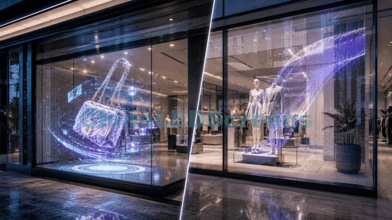
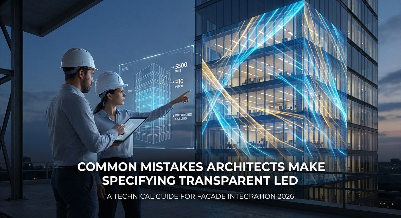
The integration of transparent LED displays into architectural facades represents one of the most significant shifts in building aesthetics of the last decade. We have moved beyond the era of static glass; the modern curtain wall is now a potential digital canvas, capable of shifting from high-transparency glazing to a vibrant media surface in milliseconds.
However, as a manufacturing and integration partner, we frequently encounter a disconnect between the architectural vision (the render) and the engineering reality (the build). Transparent LED is not merely a screen you hang; it is an active building material that dictates structural loads, thermal dynamics, and electrical infrastructure.
When these systems are specified incorrectly, the results are costly: washed-out visuals, obstructed views, maintenance nightmares, and thermal failures.
Based on years of deploying Transparent LED Displays globally, this analysis outlines the critical technical errors architects and facade engineers make during the specification phase—and how to engineer them out before construction begins.
The most prevalent error in specification documents is the demand for high resolution (low pixel pitch) combined with high transparency. In the physics of LED engineering, these two attributes are inversely correlated.
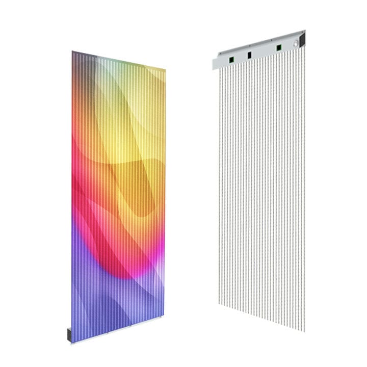
In a standard LED cabinet, the pixel pitch (the distance between LED clusters) determines the resolution. In a transparent module, the space between the pixels determines the transparency.
Architects often specify a tight pixel pitch (e.g., P2.6 or P3.9) for a large building facade, assuming “higher resolution is better.”
Calculate the Minimum Viewing Distance (MVD) before specifying pitch.
Architectural glass is designed to manage light; transparent LEDs must compete with it. A common failure mode is the installation of displays that appear brilliant at night but vanish into a ghostly haze during daylight hours.
Specifying “standard brightness” (1,500–2,500 nits) for window-facing applications, often conflating Indoor LED Screen specs with window-facing requirements.
Ambient sunlight hitting a glass facade creates immense lux levels. A screen outputting 2,500 nits cannot punch through the reflection and ambient wash of a sunny day.
For any installation facing the exterior, you must specify high-brightness DIP or high-efficiency SMD LEDs capable of at least 5,500 nits. Furthermore, the specification must include ambient light sensors and automatic dimming control. A 6,000-nit screen running at full power at night is a light pollution hazard and a traffic safety risk. The system must dynamically scale from 100% brightness at noon to 5% brightness at midnight.
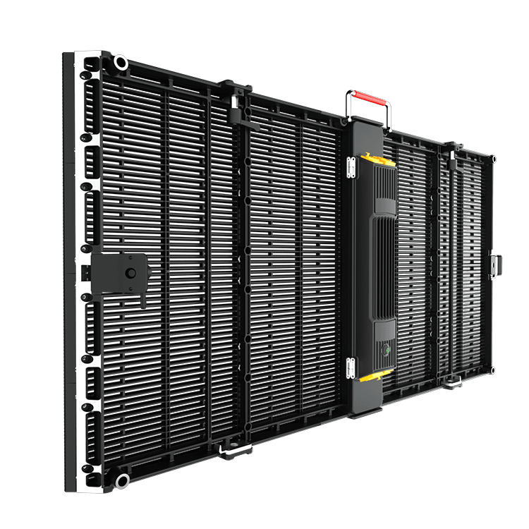
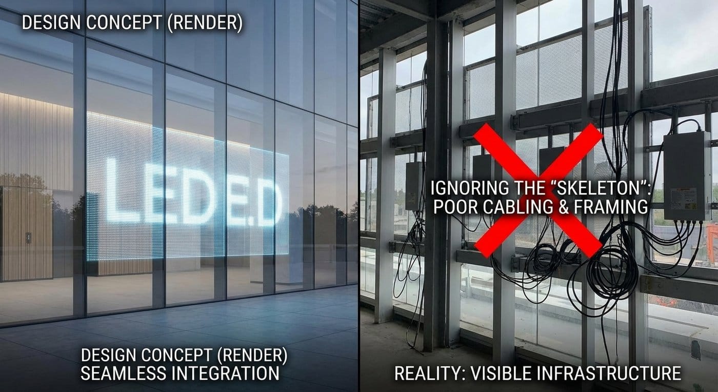
Renderings are seductive because they show floating images. Real-world installations involve power supplies, receiving cards, and CAT6 cabling. A “frameless” glass wall design often collides with the reality of where to hide the “brains” of the LED system.
Designing the glass curtain wall first and attempting to “retrofit” the transparent LED specs later. This usually results in unsightly horizontal beams, visible power boxes, and cables zip-tied to glass fins—destroying the architectural intent.
Transparent LED modules are generally 500mm or 1000mm wide. If the glass mullions (vertical framing) are spaced at 1200mm, you will have a visible vertical gap or an overlap. Additionally, every square meter of display requires power and data cables.
BIM Integration: The LED cabinet dimensions must dictate the mullion spacing, or vice versa, during the CAD/BIM stage.
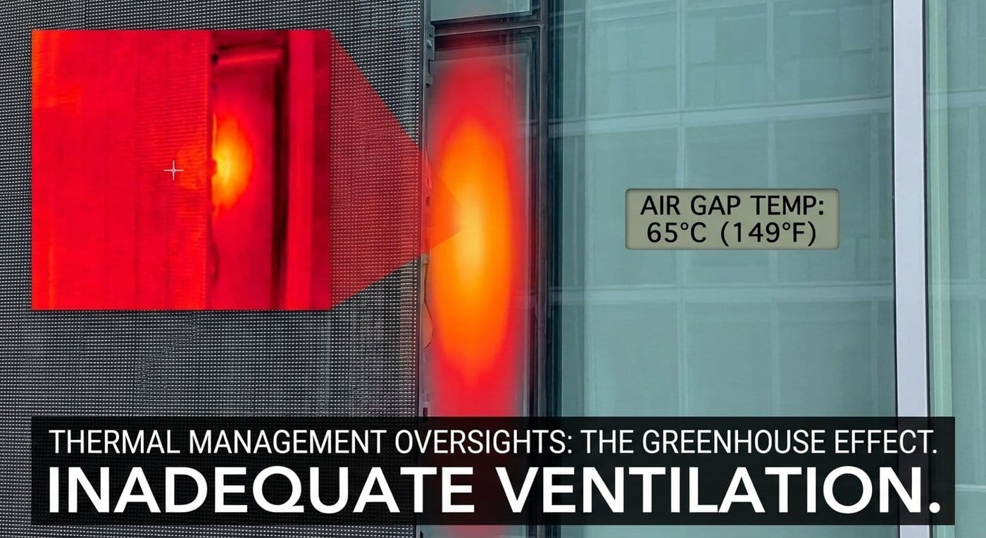
Placing an electronic device that generates heat (the LED screen) directly behind a layer of glass that traps heat (the window) creates a thermal trap.
Assuming the building’s HVAC system can handle the additional heat load of a media facade, or assuming the LED screen requires no active cooling because it is “mesh.”
While transparent screens allow airflow, the LEDs themselves can reach surface temperatures of 60°C+ during operation. When trapped behind Low-E glass, the air gap temperature can exceed the operating limits of the Driver ICs, leading to color shifting, accelerated degradation, and component failure.
A transparent LED screen is an electronic system; components will eventually need replacement. If a screen is installed 40 feet above the lobby floor behind a fixed glass wall, how do you replace a failed receiving card?
Designing “sandwich” installations where the screen is sealed between glazed units without a service plan.
If a pixel fails, you cannot disassemble the entire curtain wall to fix it.
While not strictly a hardware spec, the failure to understand how content interacts with transparency leads to underwhelming launches.
Treating the transparent display like a standard 16:9 television or Rental LED Screen.
On a transparent screen, black is transparent. Standard video content with black letterboxing or dark scenes will result in the screen looking broken or disjointed.
Architects should include a “Content Guideline” in the handover package.
To assist in correct specification, compare the architectural impact of Transparent LED against alternatives:
| Feature | Transparent LED | LED Film | Traditional LED Mesh |
|---|---|---|---|
| Brightness | High (5,000+ nits) | Low (< 3,000 nits) | High (5,000+ nits) |
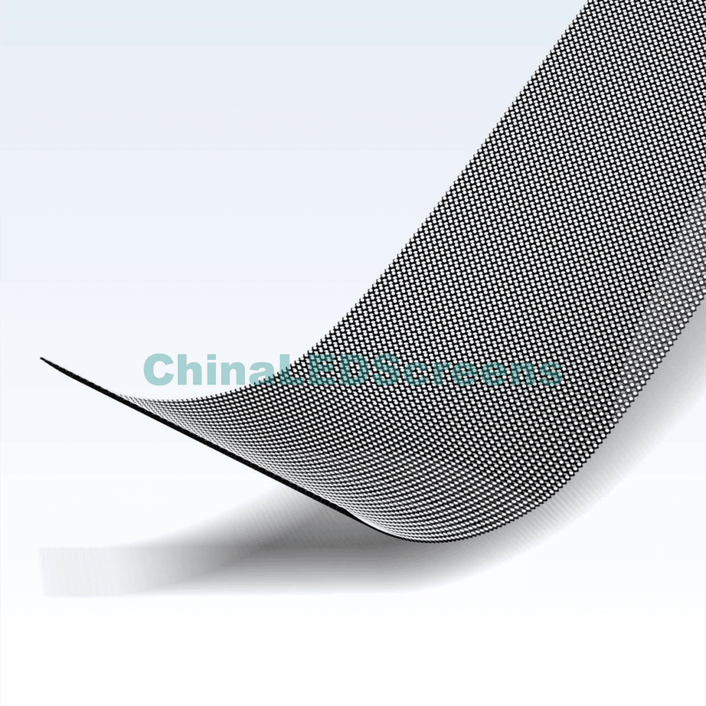
| Structure | Rigid Aluminum Bars | Flexible PCB Adhesive | Flexible Steel/Cable |
| Transparency | 60% – 90% | 85% – 95% | 30% – 60% |
| Maintenance | Module Replacement | Impossible (Peel & Replace) | Difficult (String replacement) |
| Longevity | 80,000 – 100,000 hrs | 20,000 – 40,000 hrs | 50,000 – 80,000 hrs |
| Best Use | Facades, Retail Windows | Small Retail, Elevators | Massive Building Wraps |
The most successful media architectures are those where the Transparent LED Display is treated as a core building system—integrated into the BIM models, calculated for wind and thermal loads, and aligned with the glazing geometry.
At China LED Screens, we advise architects to engage with LED manufacturers during the Schematic Design (SD) phase, not the Construction Documents (CD) phase. Early engagement allows for the customization of cabinet sizes to match mullions, the correct calculation of nits based on solar studies, and the seamless concealment of cabling.
Whether you are designing a flagship retail storefront requiring high-resolution clarity or a skyscraper requiring a massive, wind-resistant Outdoor LED Screen, the specification must follow the physics, not just the rendering.